Electrical Design
Schematic

Stepper Motors and Motor Drivers Wiring
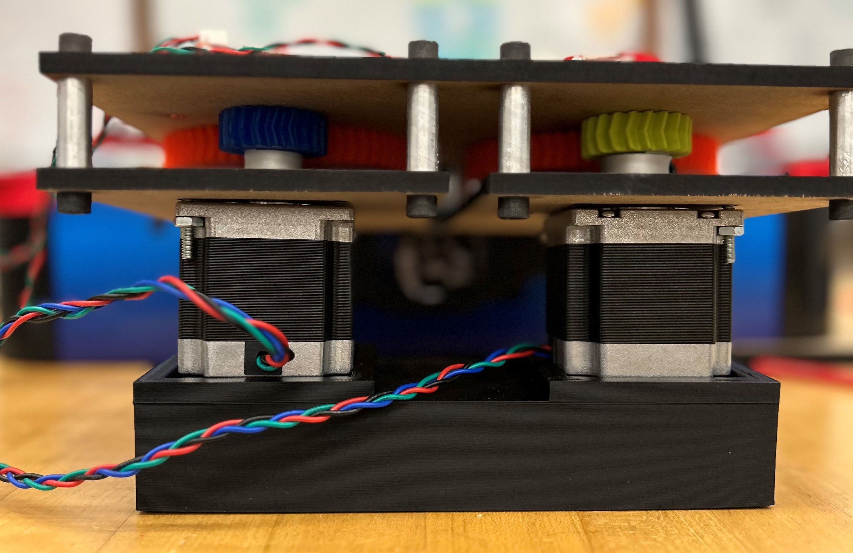
Our Main Electrical System involved 2 stepper motors that each interfaced with their own motor drivers and an Arduino Uno. We used 1.26 Nm Nema 23 stepper motors (rated 2.8/4.2 amps) and TB6600 Stepper Motor Drivers (rated for 4 amps and 9-42 volts). We chose these specific motors because they would supply enough torque to move our arm as quickly as we needed to. Additionally, we chose the TB6600 Stepper Motor Drivers to match the amperage of our motors.
Drivers to Motors:
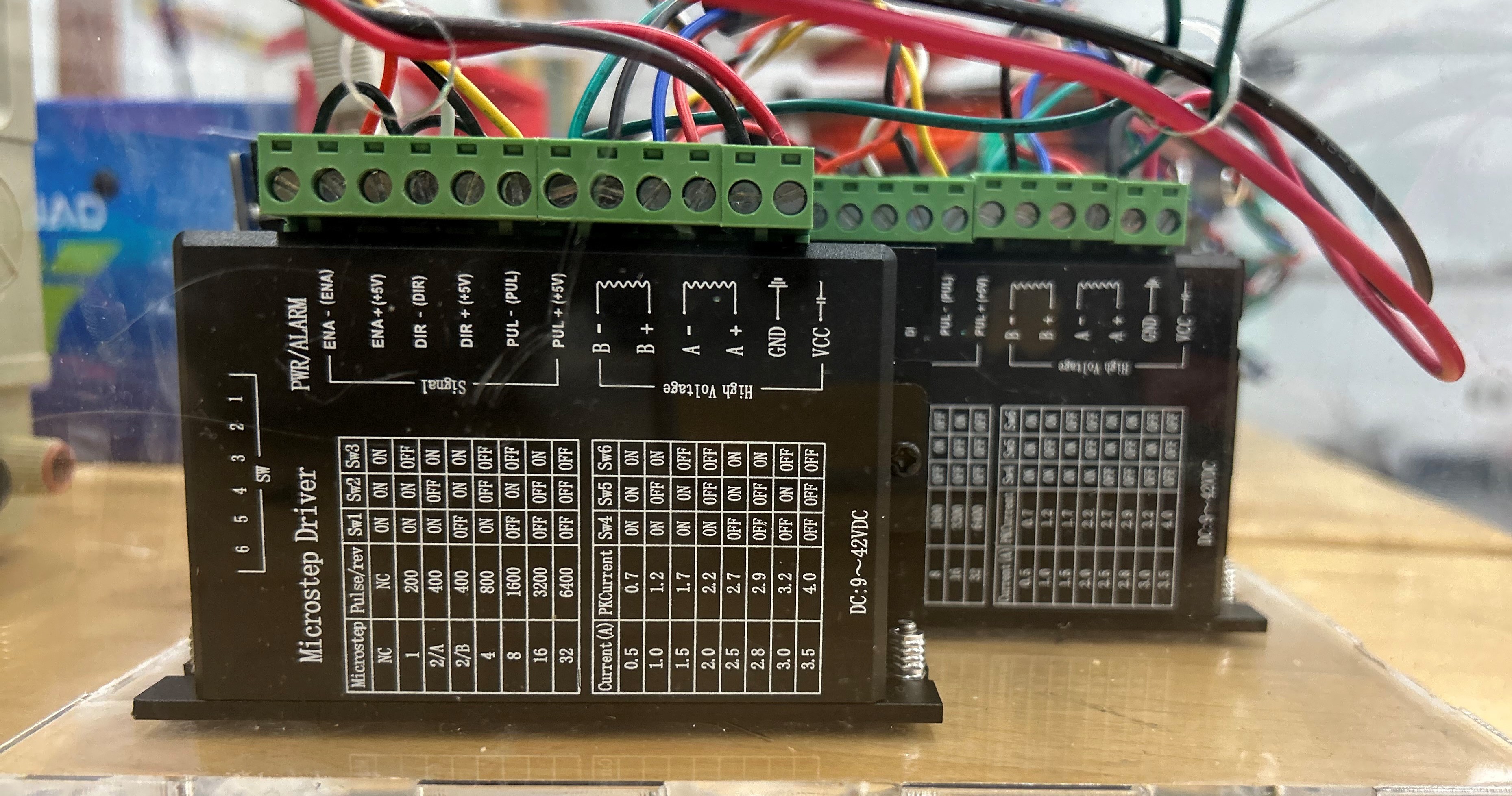
Our stepper motors were 4 wire motors so each wire is connected to an end of one of the coils inside the motor. This means that there were two pairs of wires: A+ and A- which were connected to one of the coils, and B+ and B- which were connected to the other coil. Through research and testing, we determined that the red and blue wires and the black and green wires were paired. These pairs, respectively, were wired directly to the A+, A-, B+, and B- spots on the stepper driver.
Drivers to Power:
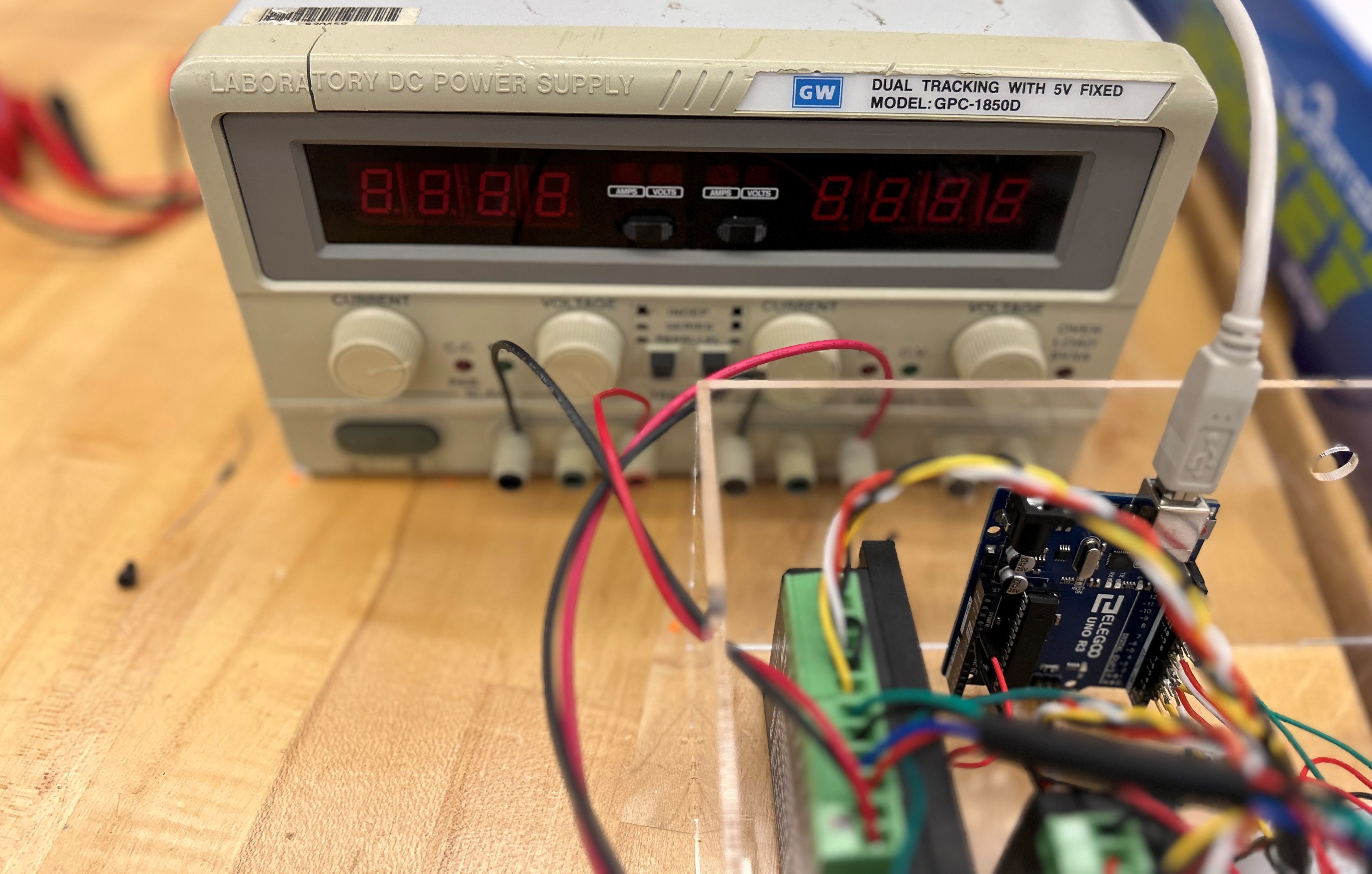
The stepper drivers were powered by an external AC to DC power supply. The VCC and GND spots on the stepper drivers were connected to separate power and ground ports on the power supply. The power supply was set so that each stepper driver could receive 18 volts and about 4 amps.
Drivers to Arduino:
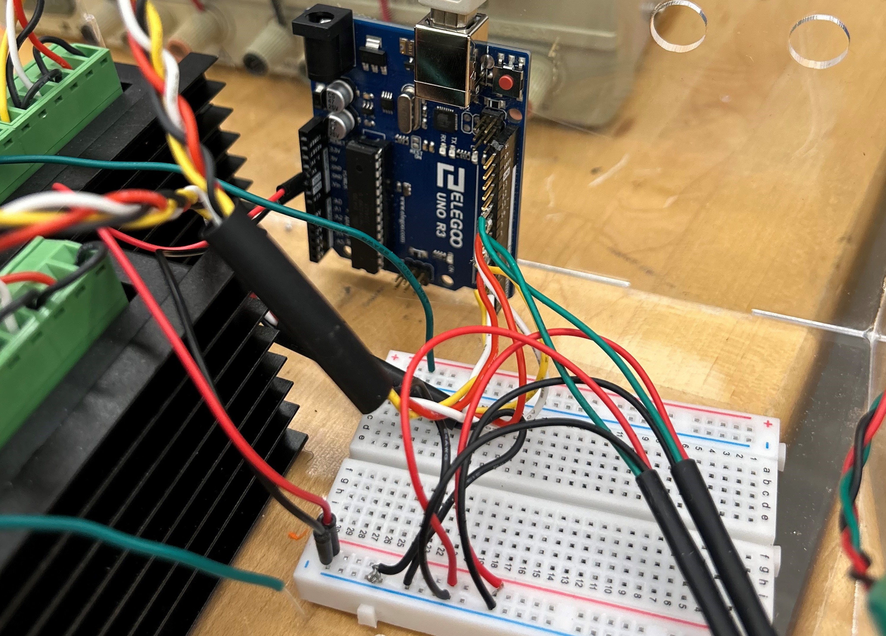
Finally, we chose to use an Arduino Uno to control the enable, direction, and pulse (step) pins on the stepper driver. To ensure that all of the grounds were the same, we connected ENA-, DIR-, and PUL- to the ground of the Arduino. ENA+, DIR+, and PUL+ for both motor drivers needed to be connected to digital pins on the Arduino. PUL+, DIR +, and ENA+ for stepper driver 1 were connected to Arduino pins D5, D6, and D7 respectively. PUL+, DIR +, and ENA+ for stepper driver 2 were connected to Arduino pins D8, D9, and D10 respectively. To prevent accidental disconnects, we soldered each wire to header pins we plugged into the Arduino.
Homing Limit Switches and E-Stop
We incorporated 2 end stops into our project so that we could home our stepper motors. We used limit switches as our end stops. Both end stop switches had power and ground that were connected to the power and ground from the Arduino. The signal lines for both end stop switches needed to be connected to digital pins of the Arduino. As such, the signal line for end stop switch 1 and 2 were connected to digital pins D11 and D12 respectively.
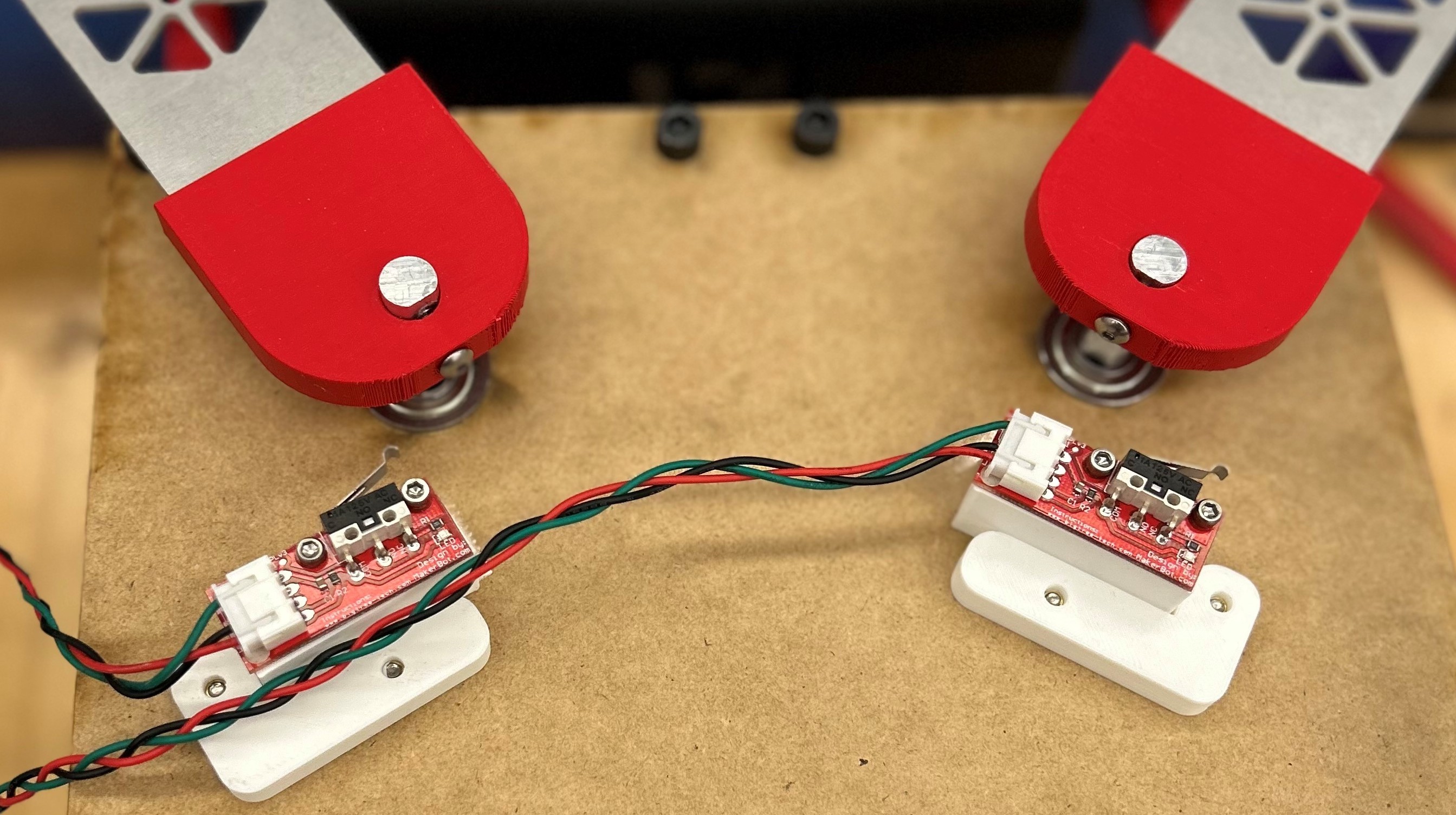
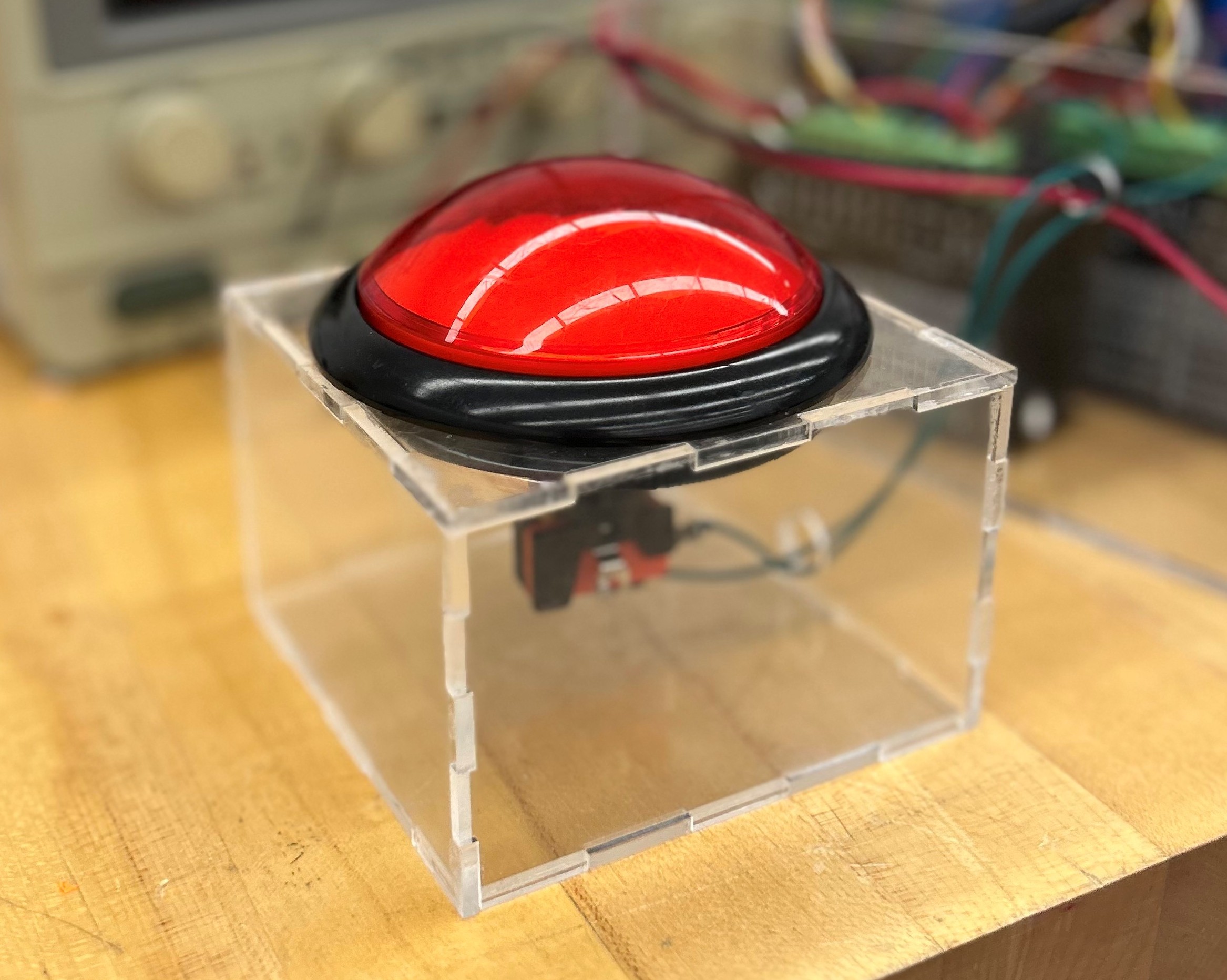
To home our stepper motors, we used two limit switch end stops each equipped with three wires: 5V power, ground, and digital signal. We connected the left and right signal wires to pins D11 and D12 on the Arduino, while power and ground were connected to 5V and GND. We also added an E-stop to stop all movement of the arm should something go wrong. To accomplish this, we connected one pin of a large red push button to Arduino interrupt pin D2 and the other pin to ground.
